Leave A Message
If you are interested in our products and want to know more details,please leave a message here,we will reply you as soon as we can.
The Isuzu Fire Truck 4HK1-TC Engine Maintenance Manual, also called Engine repair manual of Isuzu fire tender or Engineer book of Isuzu fire fighting vehicle.
The Isuzu Fire Truck 4HK1-TC engine is a high-performance diesel engine widely used in fire trucks, known for its reliability, durability and high efficiency. In order to ensure the long-term stable operation of the engine, regular maintenance and repair are essential. This article will briefly introduce the main contents of the Isuzu Fire Truck 4HK1-TC Engine Maintenance Manual to help maintenance personnel better understand and operate.
1. Engine Overview
The 4HK1-TC engine is a 4-cylinder inline turbocharged diesel engine with a displacement of 5.2 liters and a maximum power of 190 horsepower. The engine uses an advanced common rail fuel injection system and an electronic control unit (ECU) to achieve higher fuel efficiency and lower emissions.
2. Daily Maintenance
Daily maintenance is the basis for ensuring the normal operation of the engine. The maintenance manual lists in detail the items for daily inspection, including oil and coolant level inspection, air filter cleaning or replacement, fuel filter replacement, etc. In addition, the manual also provides recommendations for regular replacement of engine oil and oil filter, usually every 5,000 kilometers or every 6 months.
3. Fault Diagnosis
The maintenance manual contains a detailed fault diagnosis process to help maintenance personnel quickly locate and solve problems. The manual lists common fault codes and their meanings, and provides corresponding solutions. For example, if the engine is underpowered, the manual will guide maintenance personnel to check the fuel system, turbocharger and exhaust system, etc.
4. Overhaul and Parts Replacement
For engines that need overhaul or replacement of parts, the maintenance manual provides detailed steps and precautions. For example, when replacing key components such as piston rings, valve guides and bearings, the manual will detail the steps for removal and installation, as well as the required tools and torque specifications.
5. Safety Precautions
The maintenance manual places special emphasis on the importance of safe operation. Before performing any maintenance operations, you must ensure that the engine has been completely cooled and the power supply is disconnected. In addition, the manual also provides recommendations for the use of personal protective equipment, such as gloves, goggles and protective clothing.
Section 1A
Engine control system
Table of Contents
Page
Function and working principle
Fault diagnosis operation procedures through fault diagnostic meter
Fault diagnostic meter data list
Fault diagnostic meter data list contents
Fault diagnostic meter start failure
Fault diagnostic meter communication failure (reference)
Communication failure with ECM (reference)
Engine MIL illuminating electrical circuit system confirmation
Engine MIL blinking electrical circuit system confirmation
Exhaust gas recirculation (EGR) control system inspection
Warming-up control system inspection
Exhaust brake/ air inlet restriction control system inspection
Diagnostic trouble code (DTC) overview
DTC P0091, P0092 (Flash code 247)
DTC P0107, P0108 (Flash code 32)
DTC P0112, P0113 (Flash code 22)
DTC P0117, P0118 (Flash code 23)
DTC P0122, P0123 (Flash code 43)
DTC P0182, P0183 (Flash code 211)
DTC P0192, P0193 (Flash code 245)
DTC P0201, P0202, P0203, P0204 (Flash code 271,272,273,274)................................................... 1A-157
DTC P0217 (Flash code 542)...................................................................................................... 1A-170
DTC P0219 (Flash code 543)...................................................................................................... 1A-172
DTC P0234 (Flash code 42)........................................................................................................ 1A-175
DTC P0299 (Flash code 65)........................................................................................................ 1A-178
DTC P0335 (Flash code 15)........................................................................................................ 1A-182
DTC P0336 (Flash code 15)........................................................................................................ 1A-187
DTC P0340 (Flash code 14)........................................................................................................ 1A-190
DTC P0341 (Flash code 14)........................................................................................................ 1A-195
DTC P0380 (Flash code 66)........................................................................................................ 1A-198
DTC P0381 (Flash code 67)........................................................................................................ 1A-201
DTC P0404 (Flash code 45)........................................................................................................ 1A-205
DTC P0409 (Flash code 44)........................................................................................................ 1A-208
DTC P0477, P0478 (Flash code 46)............................................................................................. 1A-212
DTC P0500 (Flash code 25)........................................................................................................ 1A-216
DTC P0502, P0503 (Flash code 25)............................................................................................. 1A-218
DTC P0563 (Flash code 35)........................................................................................................ 1A-223
DTC P0601 (Flash code 53)........................................................................................................ 1A-225
DTC P0602 (Flash code 154)...................................................................................................... 1A-226
DTC P0604, P0606, P060B (Flash codes 153, 51, 36).................................................................... 1A-228
DTC P0641 (Flash code 55)........................................................................................................ 1A-230
DTC P0650 (Flash code 77)........................................................................................................ 1A-233
DTC P0651 (Flash code 56)........................................................................................................ 1A-237
DTC P0685, P0687 (Flash code 416)........................................................................................... 1A-241
DTC P0697 (Flash code 57)........................................................................................................ 1A-245
DTC P1093 (Flash code 227)...................................................................................................... 1A-248
DTC P1261, P1262 (Flash code 34)............................................................................................. 1A-253
DTC P1404 (Flash code 45)........................................................................................................ 1A-255
DTC P1621 (Flash code 54)........................................................................................................ 1A-257
DTC P2122, P2123 (Flash code 121)........................................................................................... 1A-258
DTC P2127, P2128 (Flash code 122)........................................................................................... 1A-264
DTC P2138 (Flash code 124)...................................................................................................... 1A-270
DTC P2146, P2149 (Flash code 158)........................................................................................... 1A-273
DTC P2228, P2229 (Flash code 71)............................................................................................. 1A-279
DTC P253A (Flash code 28)....................................................................................................... 1A-284
DTC P256A (Flash code 31)....................................................................................................... 1A-287
DTC U0073 (Flash code 84)....................................................................................................... 1A-291
Symptom diagnosis................................................................................................................... 1A-296
Phenomena: Intermittence.......................................................................................................... 1A-297
Symptom: Difficult starting........................................................................................................ 1A-300
Phenomena: Surge, unsteady idling or engine stalling.................................................................... 1A-303
Phenomena: High idling speed.................................................................................................... 1A-306
Symptom: Emergency stop......................................................................................................... 1A-307
Symptom: Emergency change..................................................................................................... 1A-309
Symptom: Under-power, acceleration failure or response lag........................................................... 1A-311
Phenomena: Intermitted operation, acceleration failure................................................................... 1A-314
Symptom: Combustion noise...................................................................................................... 1A-316
Symptom: Fuel economical efficiency low.................................................................................... 1A-317
Phenomena: black smoke from exhaust gas................................................................................... 1A-319
Symptom: White smoke from exhaust gas.................................................................................. 1A-321
Main sensor parameters.............................................................................................................. 1A-323
Special tools............................................................................................................................. 1A-325
Programme............................................................................................................................... 1A-326
Programming rule...................................................................................................................... 1A-326
Programme............................................................................................................................... 1A-326
Injection pump learning.............................................................................................................. 1A-328
Adjustment............................................................................................................................... 1A-328
Use of circuit testing tools
In the case of diagnosis according to the diagnostics program, do not use the test lamp for the power train electrical system diagnosis unless otherwise specified. In case the probe terminal will be used for the diagnostic program, please use the terminal testing adapter kit 5-8840-2835-0.
Market available electrical component
The market available electrical components mean the electrical components purchased from the market to install to the vehicle. Since these components are not taken into account during the vehicle design stage, pay attention to them when using these components.
Caution:
The market available electrical component power and ground must be connected to the circuit unconcerned to the electrical control system circuit.
Though the market available electrical components can be used, these may cause the functional fault of the electrical control system in some cases. It includes the devices not connected to the electrical system, for example, the mobile telephone, radio. Therefore, in the power train diagnosis, first check whether such market available electrical components are installed. If so, remove them from the vehicle. If the fault still exists after the componment removal, follow the general flow for diagnosis.
Damage due to ESD
Since the electronic parts in the electrical control system can work under the extremely low voltage, these are easy to be damaged due to ESD. Some electronic parts will be damaged by the static electricity below 100V that not appreciable to the human. The human appreciable ESD requires 4000V voltage. In many cases, the human will carry the static electricity, in which the friction and induction electrification is the most common.
● When the human moves side to side on the seat, it will generate the frictional electrification.
● When the human wearing the insulated shoes is near the highly electrified object, the electrostatic induction will occur at the moment of human touching the ground. The human will be electrified when the charges of the same polarity meet the charges of opposite polarity. Since the static electricity will cause damage, carefully handle the electronic parts and test them.
Caution:
Observe the following rules to prevent the damage due to ESD:
● Do not touch the ECM terminal contact pins and electronic parts soldered to ECM circuit back plate.
● Do not unpack the parks unless the preparation of part installation is finished.
● Connect the package and vehicle normal ground before taking the parts out of the package.
● If moving side to side on the seat, or sitting from standing posture or operating the part while moving in a certain distance, ensure to touch the normal ground before installing the part.
Function and working principle
Engine control (common rail) system
System overview and details
The engine control system means the electrical control system to control the engine to the optimal combustion state according to the driving condition. It consists of the following parts:
● Electronically controlled fuel injection system (common rail type)
● EGR
Besides, the engine control system includes the following system control functions.
● Warming-up control system
● Engine rotary output
● Communication and self-diagnosis function

Electronically controlled fuel injection system (common rail type)
The common rail system is provided with the pressure chamber and injector. The pressure chamber is designed to store the pressurized fuel and called the common rail; the injector is provided with the electronic control solenoid valve to inject the pressurized fuel to the combustion chamber. Since the injection control (the injection pressure, injection rate and injection time) is controlled by ECM, the common rail system allows the independent control of the engine speed and load. Even if the engine speed is low, the stable injection pressure can be maintained, which will greatly reduce the specific black smoke upon the diesel engine start and acceleration. Through this control, the exhaust gas will become clean, the exhaust volume will be less and the output will be higher.
Injection volume control
It controls the injector winding according to the signal obtained from the engine speed and accelerator pedal opening and consequently controls the fuel injection volume to achieve the best volume.
Injection pressure control
To allow the high pressure injection even if the engine speed is low, the common rail inside fuel pressure should be controlled. Work out the appropriate pressure in the common rail according to the engine speed and fuel injection volume, discharge the proper amount of fuel through the control injection pump and feed it to the common rail under pressure.
Injection time control
It substitutes the timing function and works out the appropriate fuel injection time according to the engine speed and injection volume and then controls the injector.
Injection rate control
To enhance the cylinder combustion efficiency, inject (pre-injection) a little fuel for ignition. After the ignition, carry out the second time injection (main injection). Control the injection time and injection volume through the injector (the injector coil).


Fuel System
The common rail system consists of 2 fuel pressure systems.
● Low pressure inlet line: between the fuel tank and injection pump
● High pressure line: between the injection pump and injector
The fuel is sucked into injection pump from the fuel tank and boosted in the pump to supply to the common rail. At this point, the signal from ECM controls the suction control valve (the common rail pressure regulator) to control the fuel volume supplied to the common rail.
Fuel system diagram

|
Key 1. Common Rail 2. Pressure limiting valve 3. Injector return pipe 4. Injector 5. Fuel return pipe 6. Fuel supply pipe |
7. Fuel tank 8. Breather valve 9. Starter pump 10. Fuel filter (with oil-water separator) 11. Return valve 12. Fuel injection pump |
EGR (Exhaust gas recirculation)
Egr system recycles a part of exhaust gas to the intake manifold and consequently reduces the nitrogen oxides (NOx) emission. Through the EGR system, the driving operability and exhaust gas emission reduction can be achieved. The control current from the EGR controls the solenoid valve to work and consequently control the EGR valve lift. In addition, this system detects the actual valve lift with the EGR position sensor to realize the fine control over the EGR.
EGR will start working when the engine speed, engine coolant temperature, intake temperature and barometric pressure conditions are met. Then it will work out the valve opening according to the engine speed and target fuel injection volume. Basing on the calculated valve opening, it decides the solenoid valve drive load and then drives the valve. The air intake throttle will be shut down during EGR operation to enable the intake manifold inside pressure to reach the target value.
|
|
|
|

|
Key 1. ECM 2. EGR position sensor 3. EGR valve 4. EGR cooler |
5. Intake throttle valve
|
Warming-up control
Warming-up control system
The warming-up control system is designed to ease the engine start at low temperature and reduce the white smoke and noise. With the starter switch active, ECM detects the engine coolant temperature according to the signal from the engine coolant temperature (ECT) sensor to adjust the warming-up time and achieve the appropriate starting conditions for the engine. In addition, the residual heat of warming-up can maintain the idling stable. ECM decides the warming-up time according to the engine coolant temperature to drive the warming-up relay and indicator lamp to work.

Overview of exhaust brake control
The exhaust brake exhaust pipe is provided with valve inside. Closing the valve can increase the exhaust stroke resistance and enhance the engine brake effect. The exhaust brake valve works according to the vacuum pressure. The exhaust brake vacuum pressure is controlled by the open and close of solenoid valve. ECM will enable the solenoid valve if the engine speed is above 575rpm and all the exhaust brake operating conditions are met.
Exhaust brake operating conditions
● Exhaust brake switch on
● Accelerator pedal not depressed
● Not detecting accelerator pedal position (APP) sensor abnormal, exhaust brake circuit abnormal, clutch switch abnormal, APP sensor switch abnormal, A/D switch abnormal etc.
● Clutch pedal not depressed
● System voltage above 24V
● Vehicle speed exceeding specified range
ECM
Overview of ECM

ECM monitors the information from every sensor all the time to control the power train. ECM performs system diagnostic function to detect the system operation problem, remind the driver through the engine MIL and record DTC at the same time. DTC identifies the trouble zone to help the maintenance man.
ECM functions
ECM exports 5V voltage to power various sensors and switches. However, since the power is supplied by the ECM resistance, the test lamp connected to the circuit will not be on even if the resistance is very high. In some case, the common voltmeter cannot display the correct reading since its resistance is too low. To display the correct reading, ensure to use the digital multimeter of 10MΩ input impedance at least (5-8840-2691-0). ECM controls the ground circuit or power circuit through the transistor or other unit and consequently controls the output circuit.
ECM and composition parts
ECM can achieve the high steerability and fuel efficiency while maintaining the specified waste gas exhaust. ECM monitors the engine and vehicle performance through the crankshaft position (CKP) sensor and vehicle speed sensor (VSS) etc.
ECM voltage description
ECM applies the standard voltage to each switch and sensor. This is because the ECM resistance is very high while the voltage applied to the circuit is low. The test lamp will not illuminate even if connected in the circuit. Since the input impedance of voltmeter generally used by the maintenance man is very low, sometimes the voltmeter cannot display the correct reading. In such a case, use digital multimeter of 10MΩ input impedance (5- 8840 -2691-0) to get the correct voltage reading.
The ECM input/output unit is equipped with analog-digital converter, signal damping, counter and special actuator. ECM can control most composition parts through the electronic switch.
EEPROM
EEPROM is permanent storage chip soldered to the ECM back plate. To control the power train, ECM transmits the necessary program and calibration message to EEPROM.
Different from ROM, EEPROM cannot be replaced. If EEPROM is detected abnormal, replace the ECM directly.
Considerations for ECM repair
ECM can withstand the general current relevant to vehicle driving. Do not allow the circuit overload. During the open circuit and short circuit test, do not connect the ECM circuit to the ground wire or apply the voltage unless otherwise specified. For such circuit tests, ensure to use the digital multimeter (5-8840-2691-0).

The injection pump is the core part of common rail electronic fuel injection system. The injection pump is installed to the engine front. The common rail pressure regulator and fuel temperature (FT) sensor are the composition parts of the injection pump.
The fuel is fed to the injection pump from the fuel tank through the inside supply pump (rotor type). The supply pump feeds the fuel into 2 plunger compartments in the injection pump. The fuel fed to the plunger compartment is regulated by the common rail pressure regulator. The common rail pressure regulator is only controlled by the ECM supply current. The fuel flow will reach the maximum if no current is fed to the solenoid valve. Contrarily, the fuel will stop flowing when the solenoid valve current reaches the maximum. As the engine rotates, the two plungers build high pressure in the common rail. It controls the common rail pressure regulator according to the ECM signal and consequently controls the fuel volume and pressure to the common rail. In this way, the optimal operating state can be realized to enhance the fuel economical efficiency and reduce the NOx emission.

Key
1. Fuel temperature (FT) sensor
2. Suction control valve (common rail pressure regulator)
Suction control valve (common rail pressure regulator)
ECM controls the load factor of common rail pressure regulator (the power-on time of common rail pressure regulator) to regulate the fuel volume fed to the high pressure plunger. To achieve the desired rail pressure, feed the proper amount of fuel to reduce the drive load of the injection pump. When the current is fed to the common rail pressure regulator, the variable electromotive force corresponding to the load factor will be generated to vary the fuel line opening and consequently adjust the fuel volume. When the common rail pressure regulator is switched off, the retracting spring will retract, the fuel line will completely open and the fuel will flow to the plunger (the maximum intake and maximum discharge). With the common rail pressure regulator open, the fuel line will close (normally open) under the function of the retracting spring. Through the open and close of common rail pressure regulator, the fuel corresponding to the working load rate will be supplied and then discharged from the plunger.
Fuel temperature (FT) sensor
FT sensor is installed to the injection pump and the thermistor changes the resistance along with the temperature variation. The resistance will be low if the fuel temperature is high and high if the fuel temperature is low. ECM applies 5V voltage to FT sensor through the load resistor and works out the fuel temperature according to the voltage variation to control the injection pump. The voltage will be low if the resistance is low (the temperature is high) and high if the resistance is high (the temperature is low).
Common rail

Key
1. Pressure limiting valve
2. Common rail pressure sensor
Due to the common rail type electrical control fuel injection system, the common rail is provided between the injection pump and injector to store the high pressure fuel. The pressure sensor and pressure limiting valve are installed on the common rail. The pressure sensor detects the fuel pressure in the common rail and transmits the signal to ECM. Basing on this signal, ECM controls the fuel pressure in the common rail with the injection pump common rail pressure regulator. If the common rail inside fuel pressure is too high, the pressure limiting valve will open to release the pressure.
Common rail pressure sensor
The common rail pressure sensor is installed to the common rail to detect the fuel pressure in the rail and convert the pressure into voltage signal. The higher the pressure, the higher the voltage; the lower the pressure, the lower the voltage. ECM works out the actual common rail pressure (the fuel pressure) according to the voltage signal from the sensor to control the fuel injection.
Pressure limiting valve

Key
1. Valve
2. Valve body
3. Valve guide
4. Spring
5. Housing
6. Fuel inlet
7. Fuel outlet
In the case of abnormal high pressure, the pressure limiting valve will open to release the pressure. The valve will open when the common rail inside pressure exceeds 220MPa and close when the pressure is below 50MPa. The fuel discharged from the pressure limiting valve will flow to the fuel tank.
Injector

Key
1. Wiring bolt
2. Return to the pipeline installation department
3. O-ring
4. Injection pipe installation part
5. Identification marking
6. Injector ID code
Compared to the earlier injection nozzle, the electrical control injector controlled by ECM is provided with command piston and solenoid valve. This information is recorded in the ID code (24 English numbers) to display the injector characteristics. This system controls the injection volume to achieve the optimal effect with the injector flow information (ID code). When a new injector is installed to the vehicle, ensure to enter ID code in ECM.
To enhance the injection volume accuracy, use the 2D bar code or ID code on the injector. With the code, the decentralized control injection volume can be achieved on each pressure zone to enhance the combustion rate, reduce the exhaust and provide the stable output .

● Without injection
If ECM does not power the solenoid valve through the two-way valve (TWV), it will close the outlet throttling orifice with the piston force. At this point, the fuel pressure applied to the nozzle front end will be balance with the fuel pressure applied to control room through the inlet. In this pressure balance state, the sum of pressure applied to command piston and nozzle piston gravity will be higher than the pressure applied to the nozzle front end. Therefore, the nozzle will be pushed down to close the injection hole.
● Injection
If ECM powers the solenoid valve, TWV will be pulled to open the outlet throttling orifice and the fuel will flow to the oil return port. At this point, the nozzle and command piston are lifted together with the pressure applied to the nozzle front end. Then the nozzle injection hole will open to inject the fuel.
● Injection end
When the ECM stops powering the solenoid valve, TWV will fall and the outlet opening part will close. At this point, the fuel cannot flow to the return port from the control room and the fuel pressure inside will rise quickly. Then the nozzle will be depressed by the command piston to close the injection port and then the fuel injection will stop.
Engine coolant temperature (ECT) sensor

ECT sensor is installed near the thermostat shell and the thermistor changes the resistance along with the temperature variation. The resistance will be lower if the engine coolant temperature is high and high if the engine coolant temperature is low. ECM applies 5V voltage to ECT sensor through the load resistor and works out the engine coolant temperature according to the voltage variation to control the fuel injection. The voltage will be low if the resistance is low (the temperature is high) and high if the resistance is high (the temperature is low).
Camshaft position (CMP) sensor

Key
1. Camshaft gear
2. Rotation direction
3. Camshaft position (CMP) sensor
The camshaft position (CMP) sensor is installed to the cylinder head rear section. The cam section of the camshaft generates the CMP signal when passing through the sensor. ECM determines the cylinder conditions and crankshaft angle according to the CMP signal and CKP sensor input CKP signal to control the fuel injection and calculate the engine speed. Though these controls base on CKP signal in general, they will work according to the CMP signal in the case of CKP sensor abnormal.
Crankshaft position (CKP) sensor

Key
1. Crankshaft position (CKP) sensor
The CKP sensor is installed to the flywheel housing. When the flywheel hole passes through the sensor, it will generate CKP signal. ECM determines the cylinder conditions and camshaft angle according to the CKP signal and CMP sensor input CMP signal to control the fuel injection and calculate the engine speed. Though these controls base on CKP signal in general, they will work according to the CMP signal in the case of CKP sensor abnormal.
Accelerator pedal position (APP) sensor 1

APP sensor is installed to the accelerator pedal control bracket. This sensor consists 2 sensors in one shell. ECM determines the acceleration and deceleration target value with the APP sensor. APP sensor is pin hole 1C type sensor. The signal voltage changes along with the accelerator pedal angle variation proportionably. APP sensor 1 signal voltage is low at in the early stage and increases as the pedal depressed. APP sensor 2 signal voltage is high at in the early stage and decreases as the pedal depressed.
Vehicle speed sensor

The vehicle speed sensor (VSS) is installed to the transmission. The vehicle speed sensor is equipped with HALL effect circuit. The magnet and output shaft generate the magnetic field when rotating together and then generate the pulse signal through the interaction with the magnetic field.
Atmospheric pressure sensor

The barometric pressure sensor is installed to the dashboard and changes the signal voltage along with the pressure. ECM detects the low signal voltage when the pressure is low in the high elevation area; contrarily, it detects the high signal voltage when the pressure is high. With these voltage signals, ECM can regulate the fuel injection volume and injection time to correct the elevation.
Intake air temperature (IAT) sensor

Intake air temperature (IAT) sensor
IAT sensor is installed to the guide tube between the air filter and turbocharger. When the IAT sensor temperature is low, the sensor resistance will be high. When the air temperature increases, the sensor resistance will be lower. When the sensor resistance is high, ECM will detect the high voltage on the signal circuit. When the sensor resistance is low, ECM will detect the low voltage on the signal circuit.
EGR valve

EGR valve is installed to the intake manifold. ECM controls the opening of EGR valve according to the engine operating state. According to the duty ratio signal from ECM, it controls the magnetic coil in EGR valve. Through the position sensor, it can detect the EGR valve opening. The position sensor is provided with 3 sensors in EGR valve to detect 3 locations respectively. Position sensors 1, 2, 3 are pin hole 1C type. The position sensor exports the valve open/close state in form of signal, which is in proportion with the variation of EGR valve opening.
Intake pressure sensor

The intake air pressure sensor is installed to the air inlet duct to detect the intake air pressure and convert the pressure into voltage signal. ECM detects high voltage when the pressure is high. It detects low voltage when the pressure is low. ECM works out the intake air pressure according to the voltage signal from the sensor to control the fuel injection and turbocharger.
Engine malfunction warning lamp

The engine malfunction warning lamp is installed inside the instrument to remind the driver of the engine or related system abnormal. When ECM detects abnormal through the self-diagnosis function, the engine malfunction warning lamp will be on. Short the data link connector (DLC) terminals to make the engine malfunction warning lamp blink. Then the DTC detecting state can be confirmed.
Data Link Connector (DLC)

DLC is installed to the lower left of the driver and it is the communication connector for the fault diagnostic meter and each control unit. It is provided with the diagnosis switch function. Through the short-circuit of DLC, it can enable the diagnosis switch.
Engine composition parts layout
(1/2)

|
Key 1. Engine coolant temperature (ECT) sensor 2. Injector (in cylinder head cover) 3. Injector harness middle joint |
4. EGR valve 5. Common rail pressure sensor 6. Pressure limiting valve 7. Suction control valve (common rail pressure regulator) 8. Fuel temperature (FT) sensor |
(2/2)

Key
1. Crankshaft position (CKP) sensor
2. Cam position (CMP) sensor
Engine composition parts layout 1

Key
1. ECM
2. Terminal resistor
Engine composition parts layout 3

|
Key 1. Ventilation bar rack 2. Glove box (small) 3. Heating unit, defroster control panel, A/C panel 4. Radio cassette or CD player 5. Glove box (large) 6. Windshield wiper, washer switch lever, exhaust auxiliary brake switch lever 7. Cluster switch lever 8. Steering wheel adjustment locking lever 9. Hazard warning flash lamp switch |
10. Cigarette lighter 11. Card case 12. Hook 13. Concealed type cup holder 14. Fuse box cover plate 15. Toolbox |
Circuit diagram sketch (1/2)

(2/2)
|
|
|
|
|
|
|
|
|
|
|
|
|
|
|
|
|
|
|
|
|
|

Terminal arrangement
|

ECM terminal end view
ECM

|
Joint SN |
J-14 |
|
|
Joint color |
Black |
|
|
Test adapter SN |
J-35616-64A |
|
|
Port No. |
Wire color |
Port function |
|
1 |
Black |
ECM signal ground |
|
2 |
Red |
Battery voltage |
|
3 |
Black |
ECM signal ground |
|
4 |
Black |
ECM signal ground |
|
5 |
Red |
Power voltage |
|
6 |
Blue/Red |
Malfunction Indicator Lamp (MIL) Control |
|
7 |
Blue/Pink |
Exhaust brake lamp control |
|
8 |
Light green |
Engine speed signal output to tachometer |
|
9 |
Light green/Black |
DPD indicator lamp control (Euro IV) |
|
10 |
Black/Red |
Glow plug relay control |
|
11 |
Orange/Blue |
Warming-up lamp control |
|
12 |
- |
Not used |
|
13 |
- |
Not used |
|
14 |
White/blue |
Starter on/off relay control |
|
15 |
Light green/white |
Exhaust brake solenoid valve control |
|
16 |
Blue/yellow |
Check oil residual volume warning lamp control |
|
Joint SN |
J-14 |
|
|
Joint color |
Black |
|
|
Test adapter SN |
J-35616-64A |
|
|
Port No. |
Wire color |
Port function |
|
17 |
Blue/Black |
SVS indicator lamp control (Euro IV) |
|
18 |
Blue/white |
CAN high signal input |
|
19 |
Yellow/green |
Vehicle speed sensor signal or electronic hydraulic control unit |
|
20 |
Black |
Accelerator pedal position sensor 1 shield ground |
|
21 |
Blue/Black |
ECM main relay control |
|
22 |
Green |
Air flow sensor signal low input (Euro IV) |
|
23 |
Yellow |
Air flow sensor 12V reference value (Euro IV) |
|
24 |
Yellow/Black |
Ignition voltage |
|
25 |
Red/white |
Cruise master switch signal |
|
26 |
Brown/yellow |
Clutch pedal switch signal |
|
27 |
- |
Not used |
|
28 |
- |
Not used |
|
29 |
- |
Not used |
|
30 |
- |
Not used |
|
31 |
- |
Not used |
|
32 |
- |
Not used |
|
33 |
Pink |
Refrigerating machine switch signal |
|
34 |
Green/Orange |
A/C switch signal |
|
35 |
Green/white |
Voltage dropping resistor |
|
36 |
- |
Not used |
|
37 |
Blue |
CAN lower signal input |
|
38 |
Light blue |
Keyword 2000 line data (non- Euro IV) |
|
39 |
Black |
Accelerator pedal position sensor 2 & air flow sensor (Euro IV) shield ground |
|
40 |
Blue/Black |
ECM main relay control |
|
41 |
Pink/black |
Accelerator pedal position sensor 1, idling sensor, PTO position sensor low input |
|
Joint SN |
J-14 |
|
|
Joint color |
Black |
|
|
Test adapter SN |
J-35616-64A |
|
|
Port No. |
Wire color |
Port function |
|
42 |
Red |
Accelerator pedal position sensor 1, idling sensor, PTO position sensor 5V power |
|
43 |
Black |
ECM signal ground |
|
44 |
Blue/Orange |
PTO Switch signal |
|
45 |
Light green/red |
Exhaust brake switch signal |
|
46 |
Red/white |
Ignition switch signal |
|
47 |
White /Red |
DPD switch signal (Euro IV) |
|
48 |
White/black |
Parking brake switch signal |
|
49 |
- |
Not used |
|
50 |
Black /blue |
Neutral switch signal |
|
51 |
Light green/blue |
Engine Preheat Switch signal |
|
52 |
Yellow |
Diagnosis switch |
|
53 |
Colorless/yellow |
Engine oil volume switch signal |
|
54 |
- |
Not used |
|
55 |
- |
Not used |
|
56 |
- |
Not used |
|
57 |
- |
Not used |
|
58 |
Blue/white |
CAN high signal input (Euro IV) |
|
59 |
Black |
Exhaust differential pressure sensor shield ground |
|
60 |
Black |
Accelerator pedal position sensor 2, barometric pressure sensor & intake air temperature sensor low input |
|
61 |
Red |
Accelerator pedal position sensor 2, barometric pressure sensor & air intake 5 V power |
|
62 |
Black |
ECM signal ground |
|
63 |
Blue/white |
Accelerator pedal position sensor 1 signal |
|
64 |
White |
Accelerator pedal position sensor signal |
|
65 |
|
Cruise control switch signal |
|
66 |
Blue/yellow |
Idling sensor signal |
|
67 |
Light green |
Exhaust differential pressure sensor signal (Euro IV) |
|
Joint SN |
J-14 |
|
|
Joint color |
Black |
|
|
Test adapter SN |
J-35616-64A |
|
|
Port No. |
Wire color |
Port function |
|
68 |
Black |
Optional (GND) |
|
69 |
Blue |
Air flow sensor signal (Euro IV) |
|
70 |
Brown |
PTO position sensor: |
|
71 |
Brown/green |
Barometric pressure sensor signal |
|
72 |
Red/Green |
Intake temperature sensor signal |
|
73 |
Yellow/Red |
Exhaust temperature sensor 1 signal (Euro IV) |
|
74 |
Red |
Exhaust temperature sensor 2 signal (Euro IV) |
|
75 |
- |
Not used |
|
76 |
- |
Not used |
|
77 |
- |
Not used |
|
78 |
Blue |
CAN low signal input (Euro IV or using boundary member) |
|
79 |
Black |
Exhaust differential pressure sensor, exhaust temperature sensor 1 & exhaust temperature sensor 2 low input (Euro IV) |
|
80 |
Blue/white |
Exhaust differential pressure sensor 5V power (Euro IV) |
|
81 |
Black |
ECM shell GND |


You may be interested in the following information
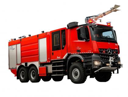
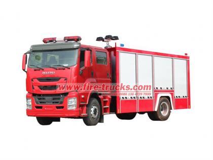
In the field of firefighting, an efficient and reliable fire truck is an indispensable and important equipment to ensure public safety. ISUZU GIGA 8cbm Water Fire Truck, as a special vehicle designed for firefighting and rescue, has become the first choice of many fire departments with its excellent performance and perfect configuration. This manual will introduce the main components, technical parameters, working principles, operation guidelines and maintenance points of this fire truck in detail, aiming to help users better understand the performance of the vehicle and ensure that they can perform tasks quickly and effectively in emergency situations. ISUZU GIGA 4x2 8cbm Water Fire Tender is a special vehicle designed for firefighting tasks. The vehicle adopts the ISUZU GIGA heavy truck chassis with strong carrying capacity and excellent performance. It is equipped with a large-capacity water tank of 8000L, which provides sufficient water source guarantee for long-term and large-scale firefighting operations. The water tank is made of high-quality carbon steel material, and the interior is specially treated to ensure the strength of the structure and effectively prevent corrosion and pollution. In terms of fire pumps, the vehicle is equipped with a CB10/60 fire pump (60L/s, 1.0MPa), which has the characteristics of large flow and high pressure. It can quickly pump water from the water tank and spray it out through a high-pressure water gun or fire cannon to effectively control the fire source. The CB10/60 fire pump is easy to operate and has stable performance. It is one of the key equipment on the fire truck. In addition to the powerful water tank and fire pump, the ISUZU GIGA 8cbm Water Fire Truck is also equipped with a PS40 fire monitor (40L/s, 0.8MPa, range ≥ 65 meters, pitch rotation -30~+70°). This fire cannon has the advantages of long range and wide coverage area. It can flexibly adjust the spray angle and flow according to different fire conditions to achieve precise fire extinguishing. At the same time, the operation of the fire cannon is also extremely simple. Firefighters can easily complete various spraying actions through a simple control handle. In other configurations of the vehicle, the ISUZU GIGA 8cbm foam water fire rescue truck also performs well. The equipment box and pump room are equipped with complete firefighting equipment, including water collectors, water distributors, water filters, water hoses, water guns, fire axes, shovels, pickaxes, wrenches, fire suits, etc., which can meet the firefighting and rescue needs of various complex fire scenes. In addition, the vehicle body is made of high-strength materials and equipped with a variety of safety protection devices to ensure safety during firefighting and rescue. When using ISUZU GIGA 8cbm Water Fire Truck, firefighters should be familiar with the various performance and operation methods of the vehicle. In particular, when pe...
Details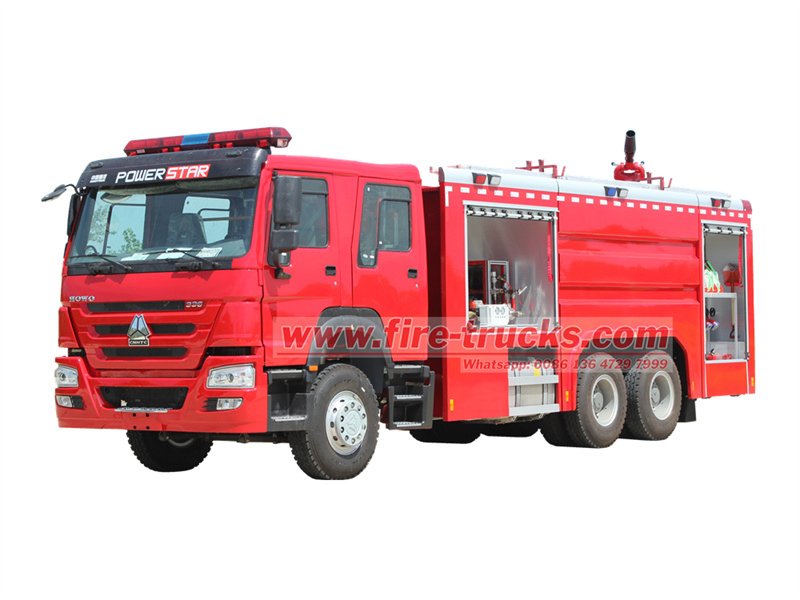
HOWO 6x4 water foam dry powder fire truck is a high-end fire fighting equipment that integrates efficient fire fighting and multi-functional rescue, and is designed to cope with complex and changeable fire scenes. This model integrates three fire extinguishing media: water, foam and dry powder, and is equipped with large-capacity storage tanks and advanced spraying equipment to ensure excellent performance in different types of fires. The vehicle adopts HOWO 6x4 chassis and WD615.69 diesel engine, which has strong power and excellent off-road performance. It can adapt to various complex road conditions and provide solid guarantee for firefighting and rescue tasks. The vehicle is equipped with a water tank with a capacity of up to 10,000L, which can continuously provide sufficient water for fire cannons to ensure the needs of long-term fire fighting operations. At the same time, the 1000L foam tank and 500L dry powder tank provide more options for dealing with different types of fires. Whether it is an oil fire, a solid material fire or a gas fire, HOWO 6x4 can respond quickly and effectively control the fire. In terms of fire-fighting equipment, the vehicle is equipped with a CB10/60-TB fire pump (rated flow 60L/s, pressure 1.0MPa), which can quickly deliver fire extinguishing agents to fire monitors. The PL8/48 fire monitor has a long range (water ≥70 meters, foam ≥60 meters), a flow of 48L/s, a pressure of 0.8MPa, and a wide coverage. The spray angle and flow can be adjusted according to the fire to achieve precise fire extinguishing. The PF5-15/40 dry powder monitor (rated flow 460L/s, pressure 0.8MPa, range ≥42 meters) is specially used for dry powder fire extinguishing. It has a compact structure, easy operation, uniform dry powder spray, and significant fire extinguishing effect. The vehicle's equipment box and pump room are equipped with a wealth of fire-fighting equipment, such as water collectors, water filters, water distributors, fire hoses, demolition tools, protective equipment, etc., providing all-round protection for firefighters. Whether it is daily training or actual rescue, HOWO 6x4 can meet various needs and become a powerful assistant for firefighters. HOWO 6x4 water foam dry powder fire truck has modular design and multi-media combination as its core advantages, and is a reliable choice for modern firefighting forces. This manual will explain in detail the main technical parameters of the vehicle, structural composition, working principle, operation process, firefighting equipment, precautions, maintenance points, common faults and treatment of fire pump system, etc., so that users can understand and operate the vehicle correctly to ensure optimal performance. Here are the manual of HOWO 6x4 Water & Foam & Powder Fire Truck ,you can download the full version at the beginning oh this article.
Details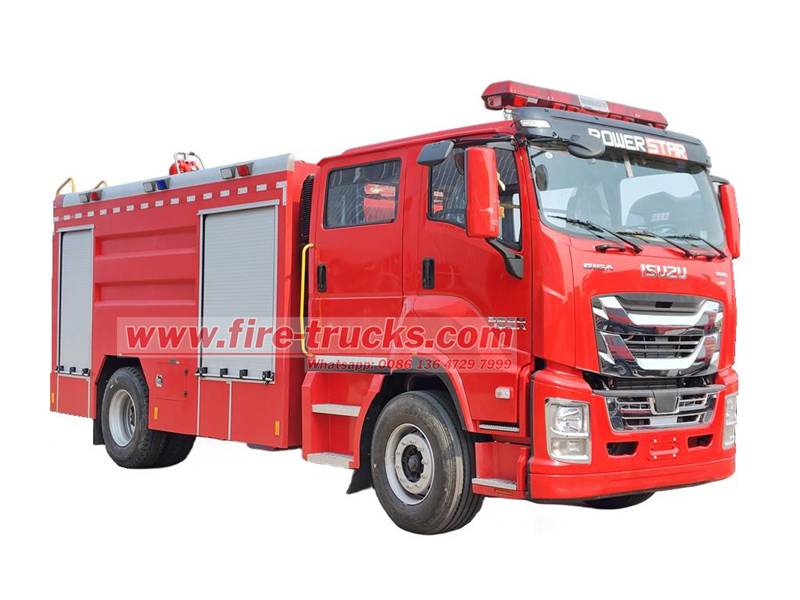
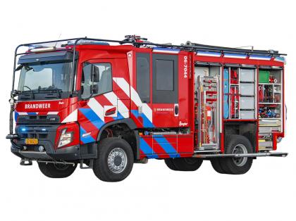
In the life-and-death moment of emergency rescue, a fire truck with excellent performance and excellent equipment is undoubtedly the most reliable comrade of firefighters. Today, we are honored to introduce you to the Isuzu GIGA 4x2 6cbm fire truck. This firefighting weapon that combines efficient power, advanced equipment and excellent control will add unlimited possibilities to your rescue operations. The Isuzu GIGA 4x2 6cbm foam fire truck, with its stable body and powerful heart-Isuzu 6UZ1-TCG61 380HP engine, has demonstrated extraordinary rescue capabilities. This engine is not only powerful and can meet the needs of various complex rescue scenarios, but also has reached the industry-leading level in fuel economy and emission control. The matching Fast 12-speed gearbox allows drivers to handle different road conditions with ease and easily achieve accurate power output. In terms of the upper body, the Isuzu GIGA 4x2 6cbm foam water tanker fire truck is equipped with a 4-cubic-meter carbon steel water tank and a 2-cubic-meter stainless steel foam tank to ensure sufficient fire extinguishing medium reserves. The pump room is equipped with a high-performance CB10/60 fire pump (60L/s), which has the characteristics of large flow and stable pressure. It can quickly transport the fire extinguishing medium to the designated location to meet the fire extinguishing needs of various fire scenes. At the same time, the pump room is also equipped with monitoring equipment such as pressure gauges and flow meters to display the working status of the pump in real time to ensure the safety and accuracy of fire extinguishing operations. The PL48 fire cannon installed on the roof has a range of ≥60 meters and a flow of 48L/s. It can remotely adjust the pitch (-15°~+75°) and horizontal rotation (0°~360°), which is suitable for high-rise buildings and large-scale fire fighting. The long range and adjustable angle have made the fire extinguishing ability of this car a qualitative leap. Whether it is a high-altitude fire source or a ground fire, it can be controlled in a timely and effective manner. In addition, the equipment box and pump room are equipped with a full range of firefighting equipment, including but not limited to water collectors, water filters, water distributors, fire hoses, water guns, foam guns, demolition tools, lighting equipment, etc., providing firefighters with all-round rescue support. The reasonable layout and easy-to-use design of these equipment further improve the rescue efficiency. At the same time, the vehicle is also equipped with advanced communication and navigation systems to ensure that it can maintain real-time contact with the command center during the rescue operation and obtain fire scene information and instructions in a timely manner. This operation manual is designed to provide you with comprehensive instructions for the use of the Isuzu GIGA foam fire rescue truck, includin...
Details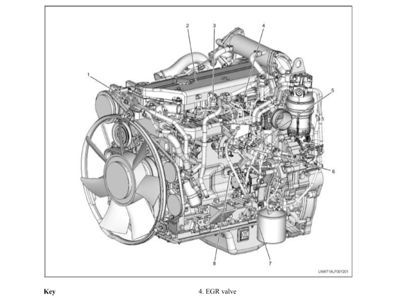
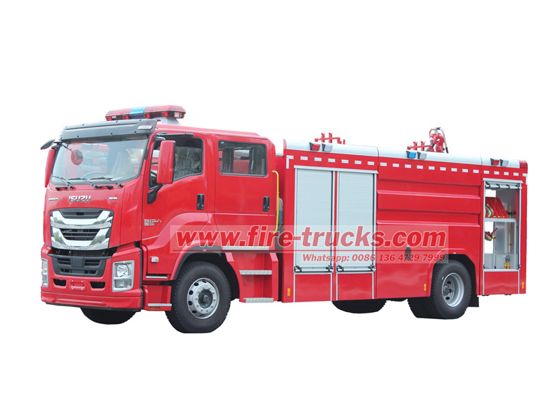
The Isuzu Fire Truck 4HK1-TC Engine Maintenance Manual, also called Engine repair manual of Isuzu fire tender or Engineer book of Isuzu fire fighting vehicle. The Isuzu Fire Truck 4HK1-TC engine is a high-performance diesel engine widely used in fire trucks, known for its reliability, durability and high efficiency. In order to ensure the long-term stable operation of the engine, regular maintenance and repair are essential. This article will briefly introduce the main contents of the Isuzu Fire Truck 4HK1-TC Engine Maintenance Manual to help maintenance personnel better understand and operate. 1. Engine Overview The 4HK1-TC engine is a 4-cylinder inline turbocharged diesel engine with a displacement of 5.2 liters and a maximum power of 190 horsepower. The engine uses an advanced common rail fuel injection system and an electronic control unit (ECU) to achieve higher fuel efficiency and lower emissions. 2. Daily Maintenance Daily maintenance is the basis for ensuring the normal operation of the engine. The maintenance manual lists in detail the items for daily inspection, including oil and coolant level inspection, air filter cleaning or replacement, fuel filter replacement, etc. In addition, the manual also provides recommendations for regular replacement of engine oil and oil filter, usually every 5,000 kilometers or every 6 months. 3. Fault Diagnosis The maintenance manual contains a detailed fault diagnosis process to help maintenance personnel quickly locate and solve problems. The manual lists common fault codes and their meanings, and provides corresponding solutions. For example, if the engine is underpowered, the manual will guide maintenance personnel to check the fuel system, turbocharger and exhaust system, etc. 4. Overhaul and Parts Replacement For engines that need overhaul or replacement of parts, the maintenance manual provides detailed steps and precautions. For example, when replacing key components such as piston rings, valve guides and bearings, the manual will detail the steps for removal and installation, as well as the required tools and torque specifications. 5. Safety Precautions The maintenance manual places special emphasis on the importance of safe operation. Before performing any maintenance operations, you must ensure that the engine has been completely cooled and the power supply is disconnected. In addition, the manual also provides recommendations for the use of personal protective equipment, such as gloves, goggles and protective clothing. Section 1A Engine control system Table of Contents Page Engine control system.. 1A-4 Precautions 1A-4 Function and working principle. 1A-5 Parts configuration diagram.. 1A-21 Circuit diagram.. 1A-25 How to diagnose the fault 1A-42 Fault diagnosis operation procedures through fault diagnostic meter 1A-48 Functional check overview.. 1A-50 Inquiry. 1A-51 Engine control system check. 1A-53 Fault diagnostic me...
Details
 IPv6 network supported
 English
 français
 Deutsch
 русский
 italiano
 español
 português
 Nederlands
 العربية
 日本語
日本語 한국의
한국의 Türkçe
 Melayu
 ไทย
ไทย Tiếng Việt
 Indonesia
  中文
中文 қазақ
қазақ Filipino
 မြန်မာ
 српски